The SeaQuest has a complex network for navigation equipment. This is due to the amount of devices in combination with the different ages of these devices. We prefer to renew the network only for parts where necessary, especially if the older parts are still performing well.
Since buying the SeaQuest, Toine has built this network step by step. Also because the previous owner had a lightning strike which caused part of the network to be repaired by an Italian shipyard. "Prutswerk" according to Toine 😎.
We can both operate the navigation equipment very well, however so far I have not studied how that is technically set up behind the screens. That's Toine's area of expertise. Actually, it's good to know something about it; for me it works well to write a blog in my own words. I learn a lot from this and it's fun to do 😊.
On the SeaQuest, the navigation equipment is all Raymarine's. The following items of equipment are installed in the cockpit outside:
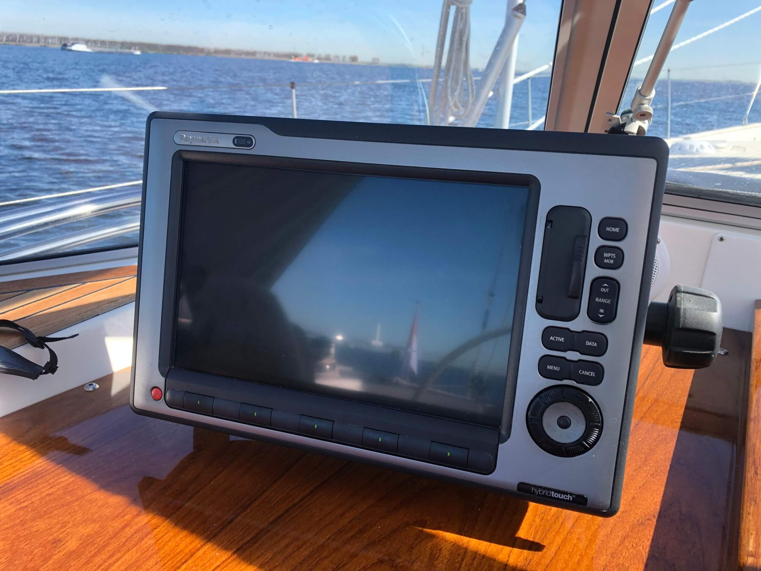
- Navigation computer with screen (E120 W) - on the chart board to the left of the cabin entrance.
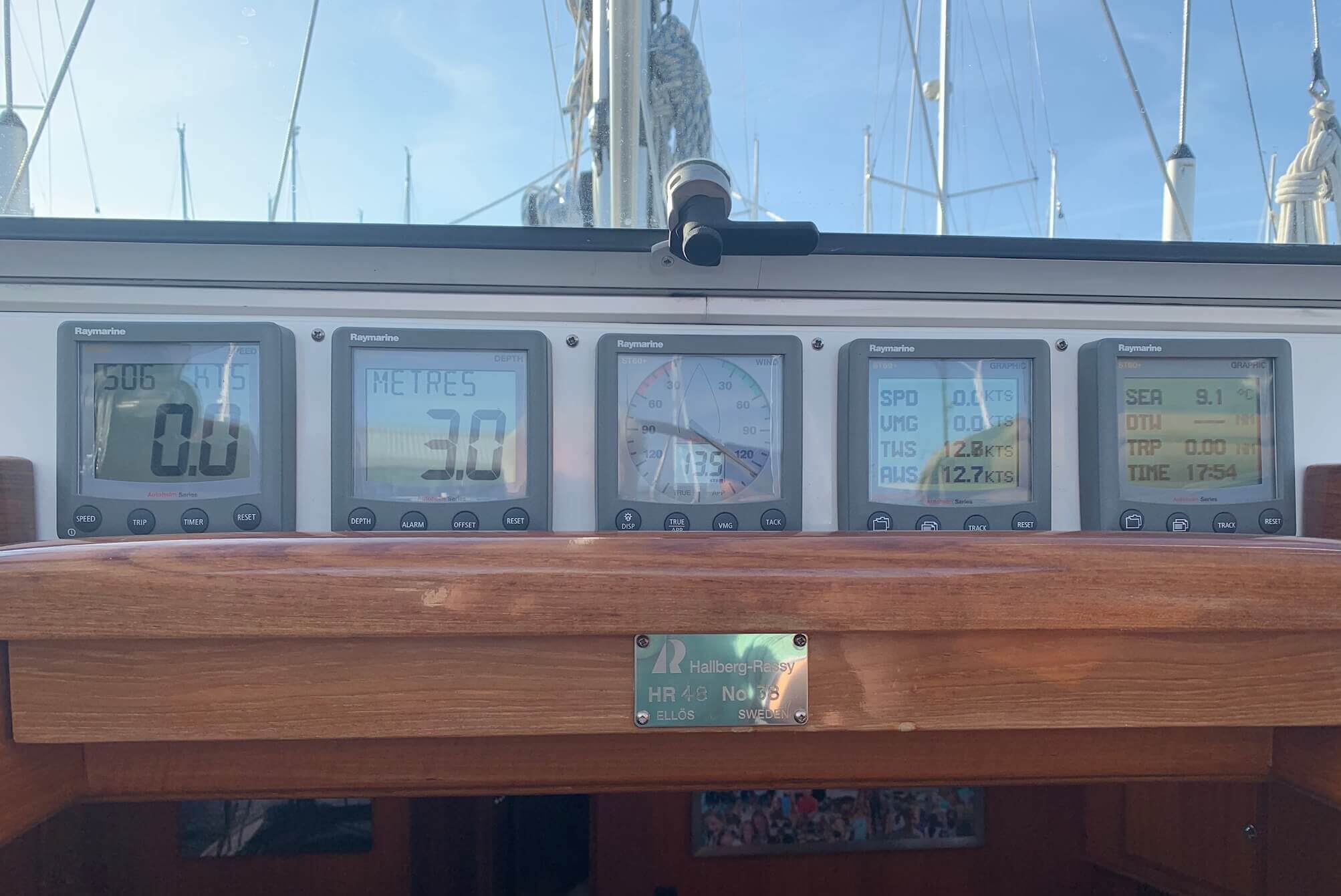
- Depth gauge.
- Speed gauge.
- Wind gauge.
- Two variable meters freely adjustable with boat information such as speed, wind, seawater temperature, time etc.
These five meters are installed next to each other above the cabin entrance.
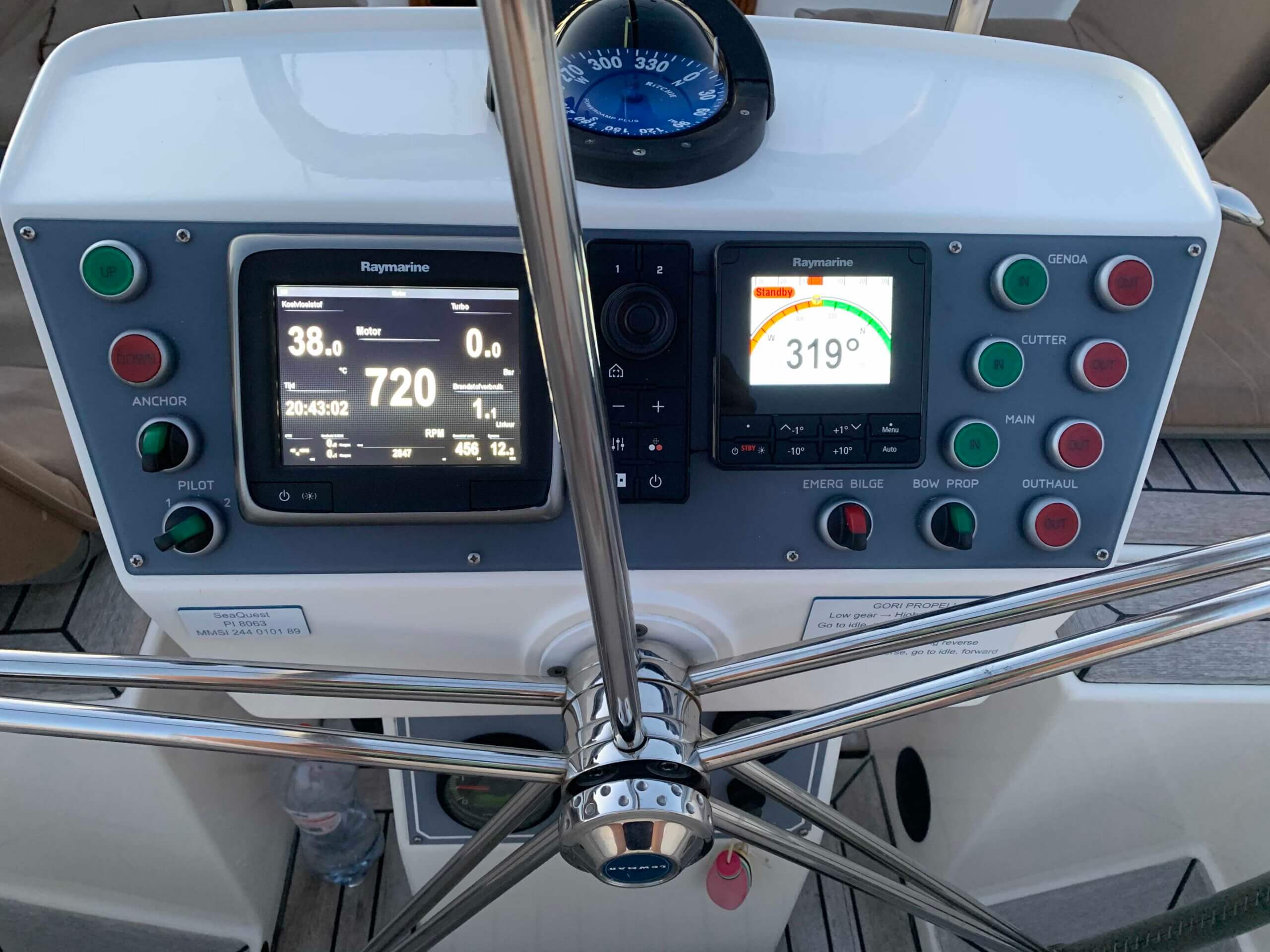
The following units are on the steering position:
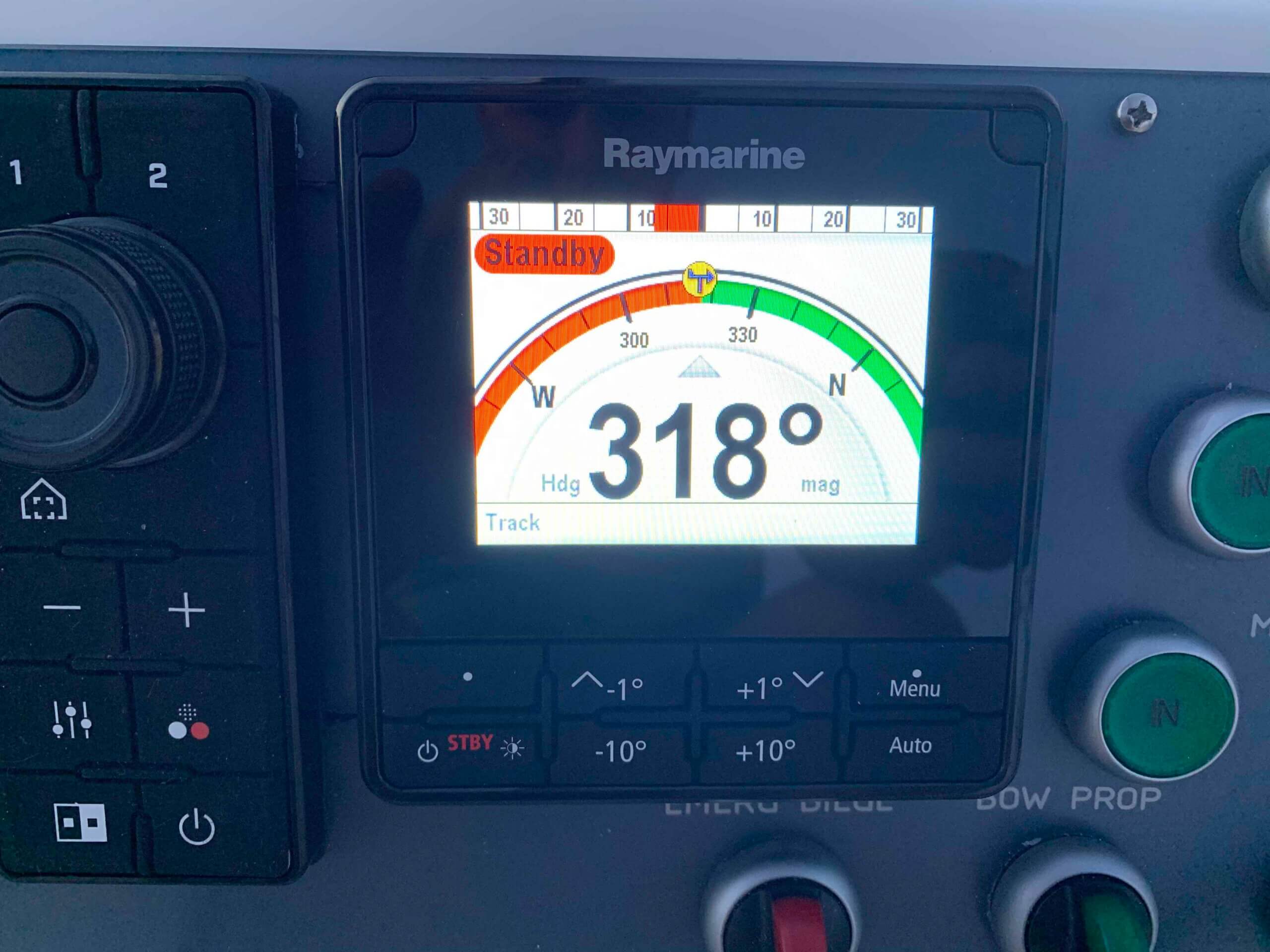
- Control panel for the autopilot (top right).
- Control panel for the thermal camera (center).
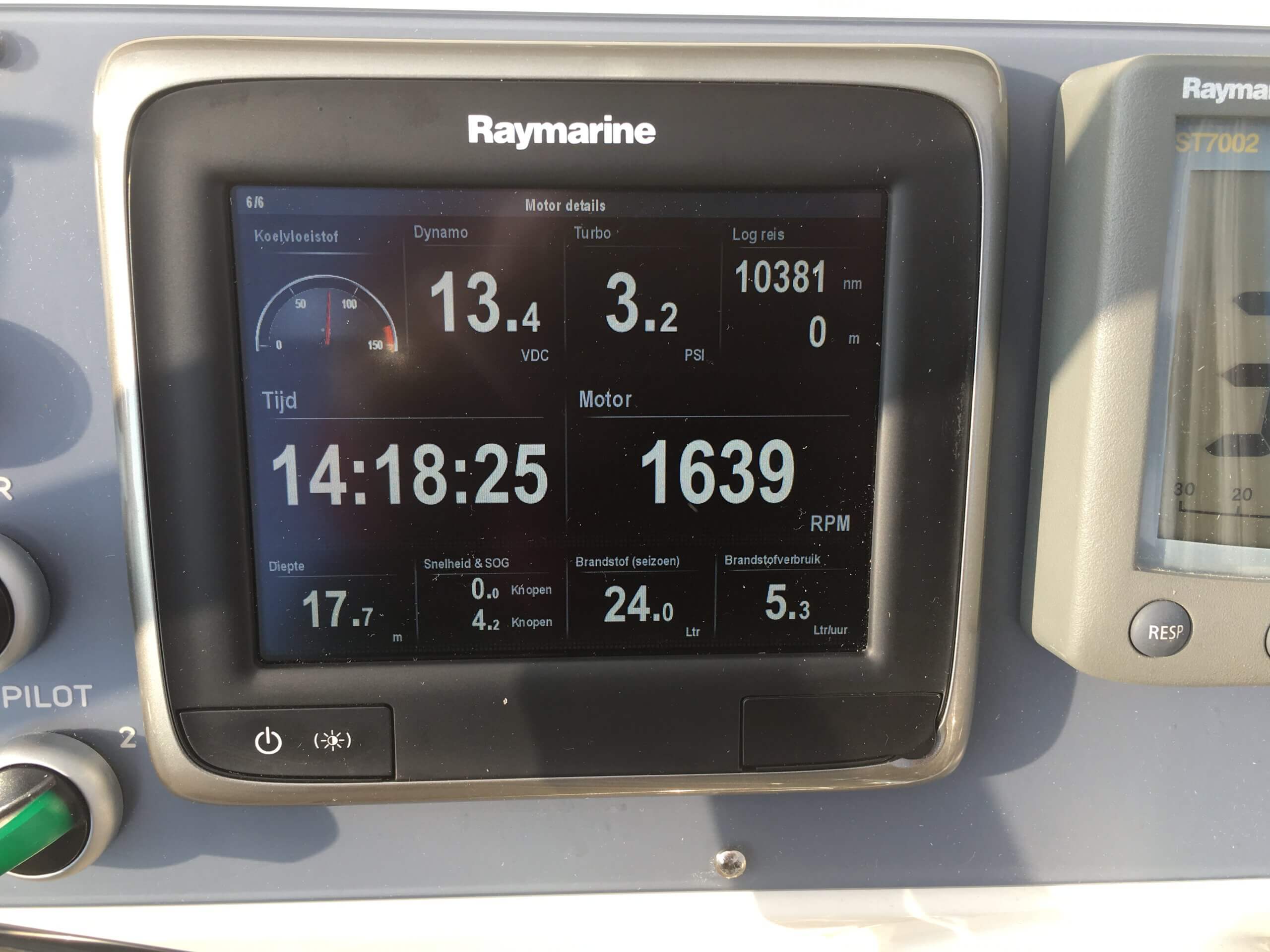
- Second navigation computer with smaller screen (A67) (top left).
We use the A67 primarily for the display of engine information (consumption, rpm, battery charge capacity, temperature and turbo pressure). In addition, it is a complete back-up for the E120.
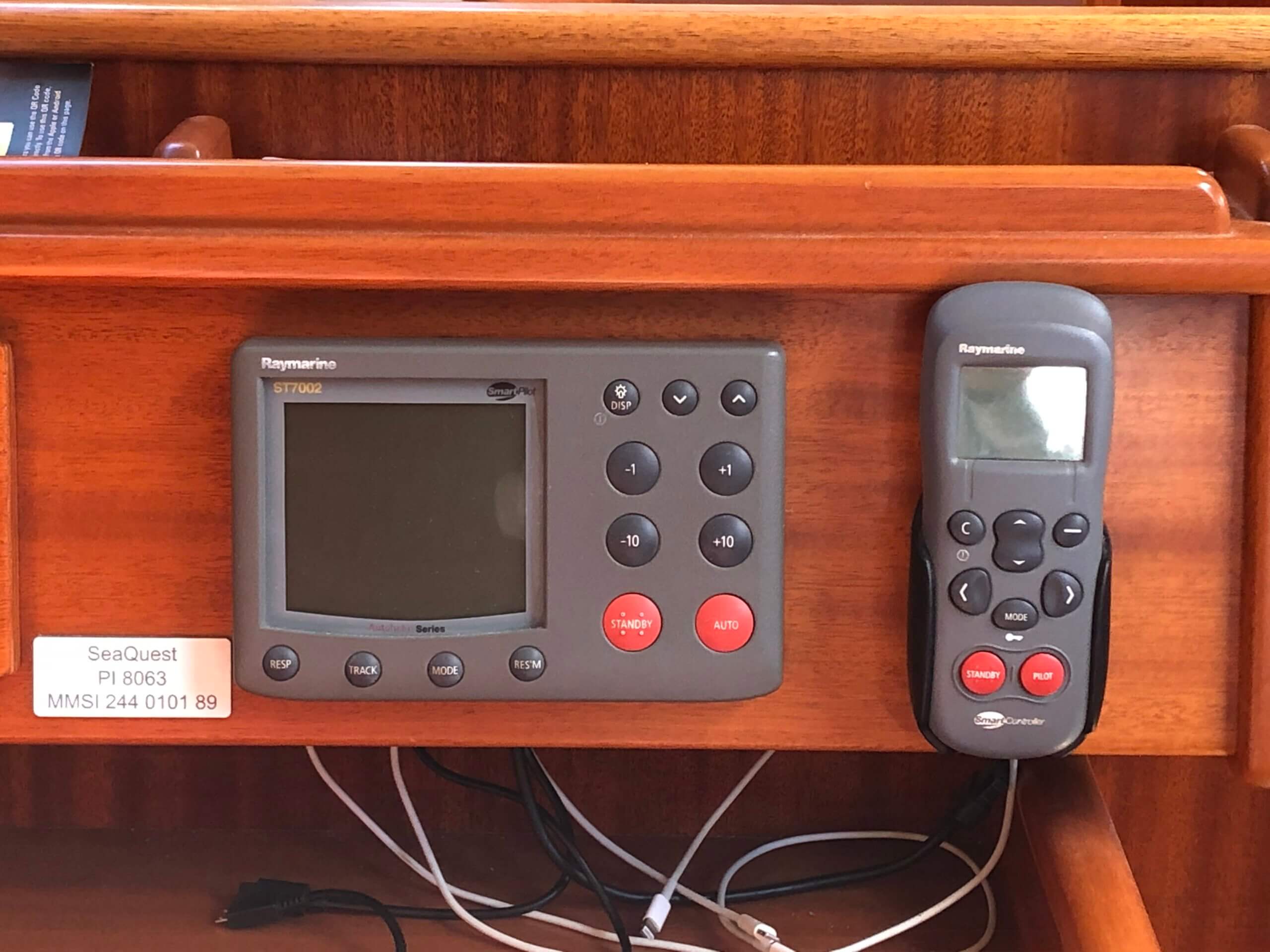
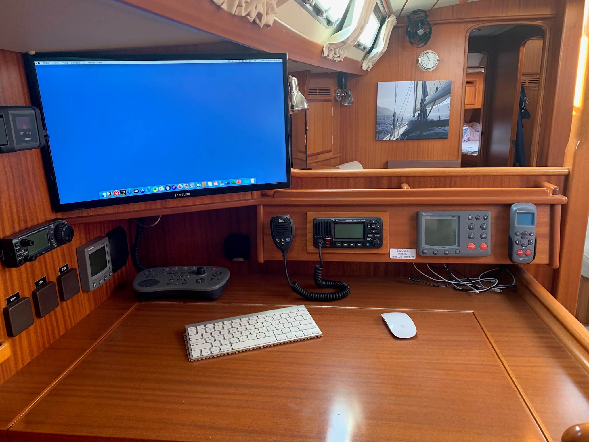
The following units are installed inside close to the card table:
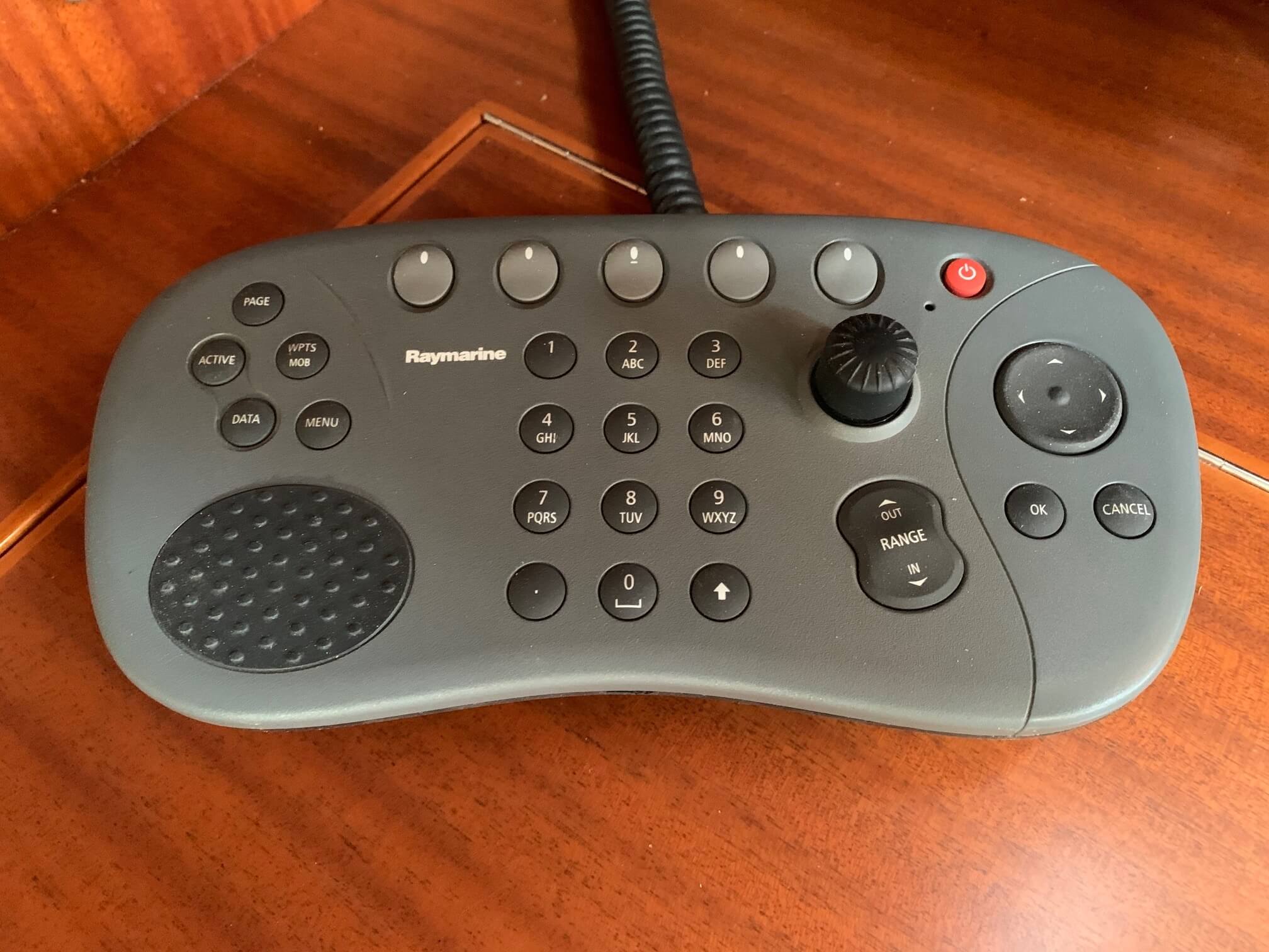
- Controls for the autopilot (when we're navigating inside and as backup for those on the steering position).
- Navigation display as repeater of the E120.
- Control panel for the E120 using the navigation screen inside.
- Variable gauge for speed, depth or wind data.
- Charger of the remote control to operate the autopilot.
In this way we can also do the navigation from the inside.
Halfway up the mast is the radar, at the top of the mast is the antenna for VHF and AIS reception, and on the first spreader is the thermal camera.
In the aft cabin are the two autopilot systems. Autopilot 1 (smartpilot S3G, 2012) with a mamba drive and autopilot 2 (EVO-400, recently purchased) with a linear drive. On the steering position is a selection button to set one of these pilots.
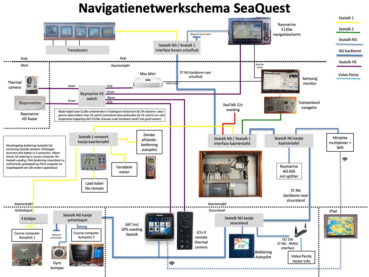
How all these devices are linked together in the navigation network is shown in the diagram below.
The E120, in combination with autopilot 2, is our main navigation component. On the E120's map we see our position and course, plot routes with waypoints and have the autopilot steer in 'track' mode to a waypoint. We also see the AIS triangles of other ships around us on that chart. We also show the radar images on this chart, either over the chart or as a separate radar screen next to the chart. We can now read and write with this device and would hardly be able to do without it. The only thing we can't receive on it is the thermal camera because the E120 is an older version; we use the newer A67 on the steering position and the iPads for that.
As backup for the E120 we have the A67 and also the Mac Mini (at the card table) and two iPads. On these iPads we have iNavX. By transmitting the complete on-board information via the miniplex to these devices, we also have our position and course on the map, AIS signals from ships around us, data about speed, wind strength/direction etc. This makes these devices also a complete navigation instrument. The A67 also transmits a wifi signal that allows us to see and control the A67 screen on the iPad via the Raymarine app. This makes it easy to have a second screen next to the E120 with some extra information, or for those who are inside during a night's sailing to take a brief look at the situation.
All these devices are in the onboard network which consists of 4 different Seatalk networks (Seatalk 1, Seatalk 2, Seatalk NG and Seatalk HS).
Seatalk NG (new generation) is the main network. It runs through the boat via a backbone (thick blue line in the network diagram above), starting from the five meters above the cabin entrance, via the chart table and the steering position to the aft cabin. Most devices are connected to Seatalk NG. Seatalk 1 and Seatalk 2 are for the older devices, and are connected to Seatalk NG via an interface. Seatalk 1 is needed for the meters above the cabin entrance, for autopilot 1, for the transmitter of the remote control of the autopilot, for the variable meter and the autopilot control at the chart table. Seatalk 2 is only needed for the keyboard of the repeater E120 screen inside at the chart table.
The Seatalk HS (high speed) network is separate from the other Seatalk networks and feeds the control of the thermal camera, the images from the radar on the E120 and the A67, and the images from the thermal camera on the A67 and via the miniplex on the Mac Mini and iPads, via the HS switch.
The network connectorblock behind the five meters above the cabin entrance has connectors for 1) the start of the NG backbone, 2) the interface between Seatalk 1 and Seatalk NG, 3) the connection to the E120 navigation screen and 4) the NG backbone to the chart table.
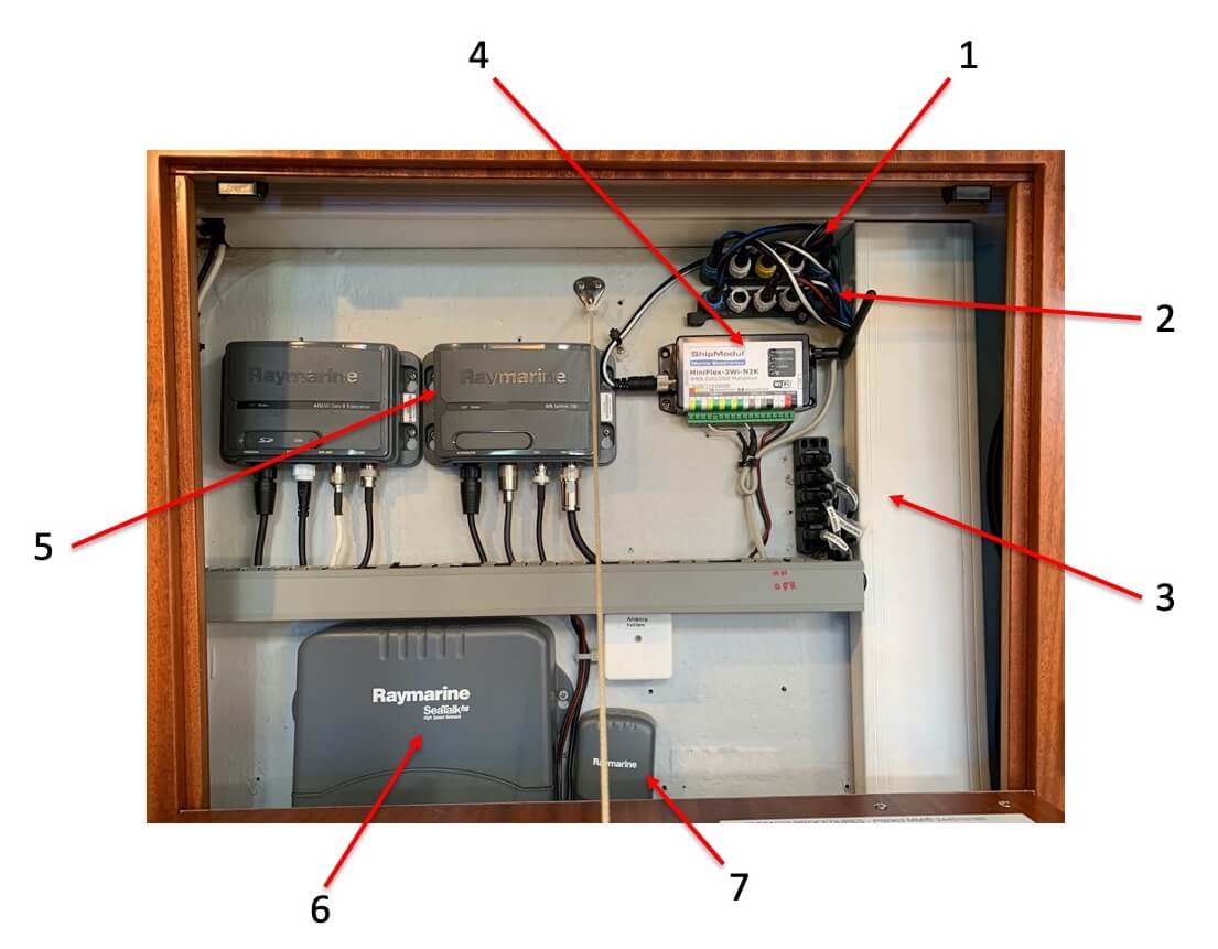
In the small cabinet next to the chart table are the following components (see the picture above):
- Network connector block with connectors for 1) NG backbone from the box above the cabin entrance, 2) 12v power supply for the Seatalk networks, 3) coupling with Seatalk 1 network box at the card table (nr 3 in the picture), 4) coupling with the keyboard at the card table and 5) NG backbone to the box underneath (nr 2 in the picture).
- Network connectorblock with connectors for 1) NG backbone to the box above (no. 1 in the picture), 2) connection to the AIS (no. 5 in the picture), connection to the miniplex and 4) NG backbone to the steering position.
- Seatalk 1 connector block for, from top to bottom, connection to 1) the Seatalk NG network, 2) antenna of the remote control of the autopilots, 3) variable meter chart table, 4) to the autopilots.
- Miniplex for wifi connection to iPads and Mac Mini.
- The AIS devices. On the right is the splitter for splitting the antenna signal to AIS and VHF. The connectors underneath are from left to right for 1) 24v power supply, 2) connection to the VHF, 3) connection to the AIS device on the left and 4) connection to the antenna. On the left is the AIS device for receiving AIS signals from other boats and sending our own AIS signal. The connectors below are from left to right for 1) 24v power supply, 2) connection with Seatalk NG, 3) connection with the AIS antenna in the ceiling near the chart table and 4) connection with the splitter.
- Seatalk HS network switch (for distributing radar and thermal camera images).
- Antenna box for the remote control of the autopilot.
The network connector block in the steering position has connectors for 1) NG backbone from the card table, 2) receiving the engine information, 3) operating the autopilot in the steering position and 4) NG backbone to the aft cabin.
The network connector block in the aft cabin has connectors for 1) NG backbone from the steering position, 2) connection to the autopilot 2 (EVO-400), 3) connection to the gyro compass for autopilot 2 and 4) NG backbone end.